Can fireproof glass be used as a structural load-bearing wall? In limited situations, yes, but ordinary fire-rated glazing cannot safely carry building loads. A load-bearing glass wall needs a complete engineered system. The glass, interlayers, framing, anchors, joints, and supporting foundation must work together.
Structural-glass engineer James O’Callaghan offers a useful warning: “Treat the glass, frame, anchors, and seals as one engineered system.” This principle matters on site. A fire-rated panel may withstand flames for a tested period, yet fail under compression, wind pressure, impact, or excessive deflection. Fire resistance is only one performance requirement.
The design process should begin with the building loads. Engineers must check vertical reactions, lateral movement, thermal expansion, edge support, and connection strength. They also need tested evidence for the exact glass and frame assembly. A beautiful transparent wall is not automatically a structural wall. That assumption can become expensive.
Some projects use laminated fire-resistant glass with steel, stainless-steel, or specially rated framing. Others transfer the main load through concealed columns, leaving the glass as an infill screen. This distinction is easy to miss. It changes the entire calculation.
The final decision depends on the product’s certification, tested dimensions, installation method, and local approval requirements. Site workmanship matters too. Small gaps, incorrect setting blocks, or weak anchors can undermine a carefully designed assembly. The honest answer is cautious: fireproof glass may participate in a load-bearing wall, but only when a qualified structural and fire engineer designs, verifies, and documents the complete system.
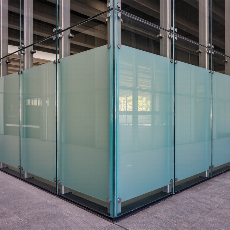
Fireproof glass plays a specific role in load-bearing wall systems. It protects against fire while preserving visibility and natural light. However, the glass usually does not carry the wall’s primary structural load. Steel, concrete, or reinforced framing transfers weight to the foundation. The glazing acts as a tested fire-resistant infill panel. This distinction matters. Treating the glass as a simple structural element can create serious design errors.
A reliable design begins with the wall’s required fire-resistance rating. Engineers should review temperature limits, impact performance, deflection, and smoke control. The glass, frame, seals, fasteners, and surrounding construction must work as one tested assembly. A strong panel can still fail if the frame twists during a fire. Small gaps matter. Movement joints also need careful detailing around floors and ceilings.
In practice, designers often place fireproof glass beside doors, stairways, atriums, or occupied corridors. These locations need protection without creating a closed, heavy appearance. The frame should resist wind, dead loads, and expected building movement. A structural engineer must verify those loads before installation. Local building requirements also control the final specification. Test reports should match the proposed dimensions and framing conditions, not merely resemble them. The approach is not perfect. Large glazed areas may increase cost, weight, and maintenance demands. Clear coordination between the architect, engineer, installer, and authority remains essential.
Fire-rated glass is generally used as an infill or curtain-wall component rather than as the primary load-bearing element. In a load-bearing wall system, structural loads are transferred through the tested steel, concrete, or engineered framing, while the glass and framing assembly provides the required fire-resistance period.
The chart shows commonly specified fire-resistance durations expressed in minutes. The actual rating depends on the complete tested assembly, including the glass, framing, seals, anchors, and installation method.
How to Use Fireproof Glass as a Load-Bearing Wall?
Structural Requirements for Load-Bearing Fire-Resistant Glass
Load-bearing fire-resistant glass must be designed as a tested wall assembly. The glass alone rarely carries the complete design load. Engineers must verify vertical loads, wind pressure, floor movement, and fire exposure together. ASTM E119 and EN 1365-1 evaluate load-bearing fire-resistance performance. EN 1364-1 mainly addresses non-load-bearing walls. Confusing these standards can create serious design gaps.
The framing system needs equal attention. Steel or aluminum members must maintain their strength during heating. Connections should transfer loads without excessive deformation. The design must also control glass deflection and thermal stress. NFPA’s Fire Loss in the United States During 2023 reported about 1,388,500 fires and $22.5 billion in direct property damage. These figures reinforce why visual transparency cannot replace tested protection. The rating belongs to the complete assembly, not the pane alone.
Tips: Request certified test evidence for the exact glass, frame, joint, and fixing method. Confirm the required fire period, such as 60 or 120 minutes. Check the load path with a structural engineer. Do not assume a thicker pane is safer. That assumption needs proof. Also review edge clearances, sealants, and floor deflection limits. Small installation changes may invalidate the tested configuration. Rechecking the details is slower, but often necessary.
| Design Dimension | Structural Requirement | Relevant Values or Classifications | Design and Verification Notes |
|---|---|---|---|
| Load-bearing concept | The glass wall must be designed as a complete structural assembly, including glass, mullions, anchors, supports, joints, and connections. | No universal load-bearing capacity applies to all fire-resistant glass. | Fire resistance and structural capacity are separate properties. A fire-rated pane should not automatically be treated as a structural wall. |
| Applied loads | Determine permanent, imposed, wind, seismic, impact, thermal, and accidental loads required by the project code. | Typical load categories include dead load, live load, lateral pressure, suction, interstory drift, and construction loads. | The structural engineer should establish load combinations and serviceability limits before selecting the glazing system. |
| Fire-resistance period | The complete wall assembly must achieve the fire-resistance period specified by the building code and authority having jurisdiction. | Common periods are 30, 60, 90, 120, and 180 minutes, depending on occupancy and separation requirements. | The tested period applies only to the tested configuration or an approved engineering extension. |
| Fire-performance classification | Select the required performance criterion rather than relying only on the term “fireproof.” | EN classifications include E for integrity, EW for integrity plus radiation control, and EI for integrity plus insulation. | A load-bearing fire wall may require both load-bearing performance and fire integrity or insulation performance. |
| Applicable fire tests | Use a test method accepted by the project jurisdiction for the intended wall type. | ASTM E119 and UL 263 are commonly used in North America; EN 1364-1 and EN 1365-1 are used for non-load-bearing and load-bearing wall tests in European practice. | A glazing-only test may not qualify a complete load-bearing wall. The framing and supporting construction must be included where required. |
| Glass composition | Use a fire-resistant glass construction specifically evaluated for the required temperature exposure and duration. | Common constructions include laminated glass with intumescent interlayers, multi-laminated glass, and insulated fire-resistant units. | The number of plies, interlayer thickness, cavity design, and edge protection affect fire performance and must match the tested system. |
| Glass thickness | Determine thickness by structural calculation, glass type, support conditions, dimensions, and the required fire rating. | Fire-resistant glazing commonly ranges from approximately 10 mm to more than 50 mm overall thickness, depending on construction and rating. | Thickness alone does not establish a fire rating or load-bearing capacity. Use the exact approved glass build-up. |
| Pane dimensions | Limit pane width, height, aspect ratio, and unsupported area according to structural calculations and the tested system. | Permitted sizes vary significantly; there is no single maximum size for all fire-resistant glass assemblies. | Larger panes increase bending stress, deflection, edge reactions, thermal effects, and handling risk. |
| Structural framing | Use a frame capable of transferring vertical and lateral loads while maintaining the required fire performance. | Framing may use protected steel, stainless steel, aluminum systems with fire-rated protection, or other tested materials. | The frame must be evaluated for strength, stiffness, thermal expansion, connection capacity, and fire exposure. |
| Vertical load path | Loads must pass continuously from the supported structure through the head, jambs, mullions, anchors, and sill into the foundation or supporting floor. | Design reactions include axial force, shear, bending moment, and local bearing at supports. | Avoid transferring structural building loads directly through unverified glass edges or setting blocks. |
| Mullion design | Mullions must resist axial compression, lateral bending, torsion, and local connection forces. | Check combined stress, buckling, deflection, and fire-induced loss of material strength. | Fire protection may reduce available dimensions and must be included in the final structural model. |
| Deflection control | Limit glass and frame deflection to prevent edge contact, seal failure, excessive stress, and loss of fire integrity. | Project limits may be expressed as an absolute value or a span ratio, such as L/240 or L/360, where permitted by the applicable code. | The governing limit must come from the structural code, tested assembly, glass standard, and system manufacturer’s engineering data. |
| Edge support and bite | Provide continuous, dimensionally stable edge support and the minimum glass bite required by the tested system. | Glass bite is system-specific and may vary with glass size, load, framing, and fire-rating requirements. | Do not reduce bite, alter glazing blocks, or substitute gaskets without documented approval. |
| Joints and seals | Perimeter joints, mullion joints, and interfaces with floors and ceilings must maintain fire, smoke, movement, and weather performance. | Joint width is determined by expected movement, construction tolerances, and the tested firestop design. | Use only sealants, gaskets, backer materials, and firestop components approved for the assembly. |
| Thermal expansion | Allow differential movement between glass, frame, floor slabs, and adjacent construction without imposing unintended restraint. | Movement may result from temperature change, fire exposure, seismic drift, live-load deflection, and building settlement. | Movement joints must be compatible with the fire-tested perimeter condition. |
| Connection design | Design anchors, bolts, welds, brackets, and embedments for strength, stiffness, corrosion resistance, and fire exposure. | Connection checks include tension, shear, combined loading, edge distance, pull-out, and prying effects. | Connections are part of the load path and should be covered by structural calculations and fire-protection details. |
| Impact and safety glazing | Where human impact is possible, the glass must also satisfy the applicable safety-glazing requirements. | Relevant requirements may include laminated-glass retention or impact classifications under the local building code. | Fire resistance does not automatically mean impact safety, fall protection, or blast resistance. |
| Inspection and maintenance | Inspect glass, framing, joints, fasteners, gaskets, and firestop interfaces throughout the service life. | Check for cracks, delamination, seal deterioration, corrosion, distortion, displacement, and unauthorized modifications. | Any damaged or altered component may invalidate the tested fire-resistance configuration and require professional evaluation. |
| Required documentation | Maintain calculations, shop drawings, fire-test reports, installation instructions, product certificates, and inspection records. | Documentation should identify glass build-up, frame type, dimensions, supports, joint details, rating, and permitted applications. | Final acceptance normally requires review by the project structural engineer, fire-safety professional, and authority having jurisdiction. |
A fireproof glass wall must be designed as a tested structural assembly, not as ordinary glazing. Fire-rated glass may resist flames and heat, but that does not automatically make it load bearing. Confirm whether the selected system carries vertical loads, lateral pressure, or only its own weight. A licensed structural and fire engineer should review the design before fabrication.
Glass selection depends on the required fire rating, impact exposure, size, and transparency. Fire-resistive glass can limit heat transfer, while fire-protective glass usually provides a narrower level of protection. Large panels may need thicker laminated or multi-layer construction. Check the tested limits carefully. Bigger is not always better.
The frame matters just as much. Use steel or other approved framing with compatible fire-rated gaskets, setting blocks, fasteners, and perimeter seals. Anchors must transfer loads into the surrounding structure without crushing the glass. Allow controlled head deflection; rigid connections can create unexpected stress. The wall also needs movement joints where the building expands or settles.
Supporting components are easy to overlook. Mullions, transoms, sill angles, and backing plates should match the tested assembly. Site tolerances matter. A small gap can become a serious weakness during a fire. I would also question any design that relies on untested substitutions. A visually similar frame may perform very differently. The safest specification identifies the complete assembly, its test evidence, installation limits, and inspection requirements. Loose assumptions remain the weakest component.
How to Use Fireproof Glass as a Load-Bearing Wall?
Designing a load-bearing fire-rated glass wall begins with the load path, not the glass selection. A structural engineer should calculate dead, live, wind, seismic, and impact loads first. The supporting slab, head, posts, and connections must transfer forces safely around the glazing. Fire-rated glass is usually a tested assembly, not an independent column. That distinction matters.
NFPA’s Fire Loss in the United States During 2023 reported approximately 1,388,500 fires and 3,670 civilian fire deaths. These figures justify careful compartment design. Specify the required fire-resistance period, such as 60 or 120 minutes, from the building code and the authority having jurisdiction. Then select a complete tested system meeting standards such as ASTM E119 or UL 263. The glass, framing, seals, setting blocks, and anchors must match the tested configuration. Mixing components can invalidate performance.
Installation should follow a controlled sequence. Survey the opening and confirm tolerances before fabrication. Install the structural frame, checking plumb, level, and anchor torque. Add approved fire-rated spacers and setting blocks. Lower each panel without twisting its edges. Keep the designed perimeter gap clear of mortar and debris. Seal joints with compatible fire-rated materials. Finally, inspect every connection and record photographs, product documents, and test references.
I would not call ordinary laminated glass “fireproof.” That wording can mislead clients. A small alignment error may create a large failure. Independent inspection is worth the cost, especially where the wall supports a roof, floor, or occupied space. Industry guidance often emphasizes tested assemblies, yet field conditions rarely look perfect. That is where the design needs honest review.
How to Use Fireproof Glass as a Load-Bearing Wall?
Testing, Inspection, and Maintenance of Fireproof Structural Walls
Fireproof glass must be evaluated as part of a complete structural wall assembly. The glass alone cannot prove fire resistance. Engineers should review framing, supports, joints, seals, and anchorage together. Load calculations must include wind pressure, floor movement, impact risk, and the glass’s heated deflection. A full-scale test is more reliable than a material sample. It should reproduce the expected load and fire exposure. Small details matter.
During inspection, check the glass surface for chips, scratches, clouding, or unexpected discoloration. Examine gaskets and fire-rated sealants around every edge. Look for gaps near anchors, loose fasteners, and frame distortion. A narrow opening can allow hot gases to pass. Temperature records and test certificates should match the installed wall. They should also identify the tested dimensions and support conditions. Do not assume similar-looking glass performs similarly.
Maintenance should follow a written schedule, with closer reviews after construction movement or nearby impact. Clean surfaces with approved methods and avoid abrasive tools. Record photographs, measurements, repairs, and changes in building loads. Any damaged panel should be assessed by a qualified engineer before replacement. I have seen inspection plans focus heavily on glass and overlook the frame. That weakness deserves correction. Not every problem is visible. Retesting may be necessary when the design, support, or joint detail changes.
It can be part of a structural wall assembly, but the glass usually cannot act as an independent column. A structural engineer must design the load path. Supports, frames, anchors, and connections carry forces around the glass.
Calculations should include dead, live, wind, seismic, impact, and building movement loads. Heated glass deflection also matters during a fire. Small movements can stress edges and seals.
The building code and local authority determine the required period. Common periods include 60 or 120 minutes. The complete wall assembly must meet the required fire exposure and structural conditions.
Fire resistance depends on the glass, framing, spacers, setting blocks, seals, and anchors together. Similar-looking materials may perform differently. Mixing untested components can weaken the result.
Survey the opening and confirm its dimensions and tolerances. Check the slab, head, posts, and anchor locations. Fabrication should begin only after these conditions are verified.
Check the frame for plumb, level, and correct anchor torque. Lower each panel without twisting its edges. Keep the perimeter gap clear of mortar and debris. Use compatible fire-rated seals.
Inspect chips, scratches, clouding, discoloration, loose fasteners, frame distortion, and damaged gaskets. Check every edge and anchor area. A narrow gap may let hot gases pass.
Use a written inspection schedule, especially after building movement or nearby impact. Clean with approved methods and avoid abrasive tools. Record photographs, measurements, repairs, and load changes.
A qualified engineer should assess any damaged panel before replacement. Retesting may be necessary after changing the support, joint detail, or wall dimensions. Not every problem is visible.
No. Calling it “fireproof” can mislead clients. Fire performance requires verified evidence for the complete installed assembly. I would question any claim based only on the glass label.
Can fireproof glass be used as a structural load-bearing wall? In carefully engineered systems, fireproof glass may contribute to a load-bearing or structural wall assembly, but it cannot be treated like ordinary glass. Its suitability depends on verified fire resistance, load capacity, dimensions, support conditions, thermal performance, and compatibility with the surrounding frame. The complete assembly—including glass, framing, fasteners, seals, and connections—must be designed to transfer vertical and lateral loads safely while maintaining fire separation.
Designers should select the appropriate fire-resistant glass type and supporting components according to the project’s structural and fire-safety requirements. Installation must follow approved drawings, with precise alignment, controlled tolerances, suitable setting materials, and protected joints. Before use, the wall system should undergo applicable fire, impact, structural, and integrity testing. Regular inspections should check for cracks, frame movement, damaged seals, corrosion, or unauthorized modifications. Proper documentation, professional installation, and scheduled maintenance are essential for long-term safety and performance.

DotView Glass